

The irrelevant history.
Many moons ago I was working on the volumetric/probe based lighting of Call of Duty Black Ops 3. I wrote about it a few times already, but the Tl;Dr is that baked lighting for that game was computed from a dense grid of diffuse irradiance probes (imagine them as 1-texel per face cubemaps) coupled with a "specular" (pre-convolved GGX...) probe (of the parallax-corrected variant, using k-DOPs as the proxy shape) per lighting volume (artists could place any amount, nest them and so on).
This system worked well, but it required some rather arcane math to "integrate" all this information into a single lighting value in a way that the various components helped each other (a process sometimes known as probe re-normalization) - and at the time, the rendering lead for the game (Dimitar Lazarov) opined that there must be a better way, specifically, a way to directly "warp" the data from the high resolution specular probe in a way to be correct at any point is space in the lighting volume.
Unfortunately, such a solution did not seem immediately obvious, and I didn't have enough time, so in the end the game shipped with some smart renormalization math, but nothing more.
I do believe though that Dimitar's intuition was right, and specifically, in the case of a baked-lighting solution, I think it would be smart to use some optimization process to fit some corrective factors directly into the dense grid, instead of trying the arcane incantations required to make two lighting signals at different spatial and angular resolutions "come together". And these correctives might include a way to "warp" the sampling of the specular data...
The problem at hand.
Now, take the word salad I wrote above, and throw it away - because the problem I tried to solve here is (a bit) different - and it's part of a bigger idea I'll maybe write about in the future (assuming I have the time to work on it and all the pieces fall in line). It's still using probes (think - cubemaps and similar), but instead of storing in them only lighting or other attributes, we also record per texel the scene depth.
Here is the problem: I want then to use the information from a probe baked at a given location, to approximate the results I would have gotten at a different location, reprojecting the data.
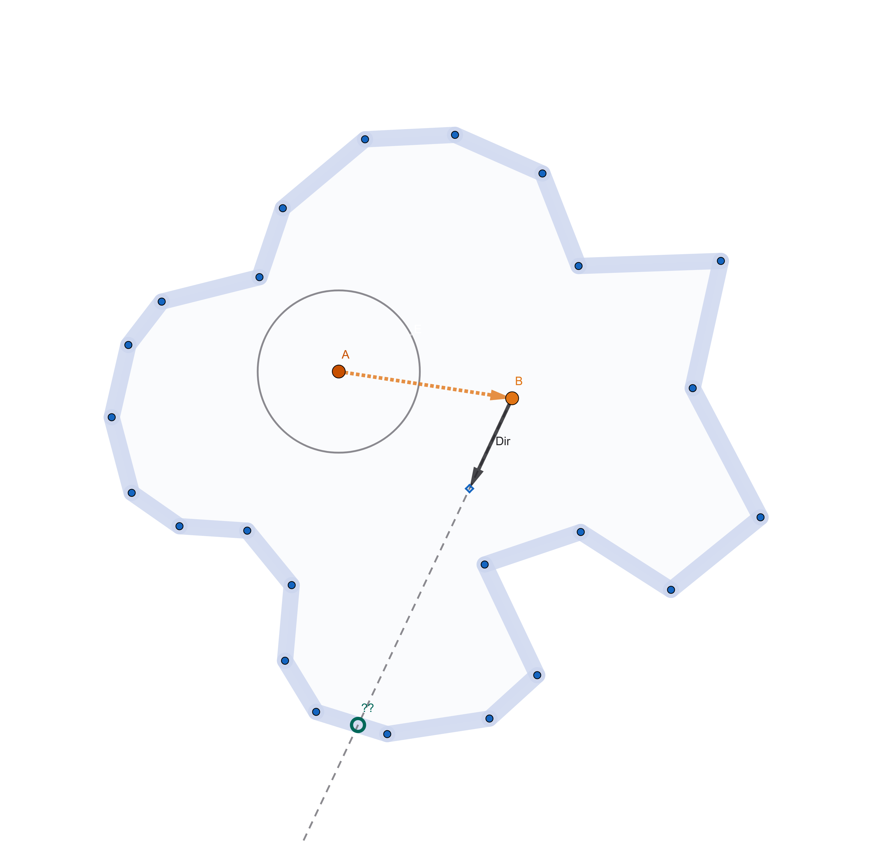 A probe at location A captures the scene all around it - we want to be able to approximate the intersection of any ray from a new location B using the data baked at A
A sidenote - every time you store depth from a rasterizer, you can think of the resulting image as an efficient way of storing a bunch of rays, all with the same origin. Spherical probes are particularly interesting then, because of how much efficiently they encode data, with only a few you can cover most of the surfaces in
your scene.
Now, obviously you could solve our problem by... literal reprojection. The probe is equivalent to a point cloud, you can take each point and "scatter" it to the appropriate texel in the destination probe. You'll need a compute shader, atomics to depth-test (can use the trick of encoding both depth and payload in a single 64bit number, put the depth in the most significant bits... or do two passes) and you'll end up with holes you can fill in various ways (probably best would be something like a push-pull mip pyramid).
Ok - boring, we know how to do that... can we do something else? We could raymarch, but it would be dumb - even slower than scattering. Anything else?
Here is where I remembered the story above... There must be a way to warp a probe to approximate a different location in space! Right?
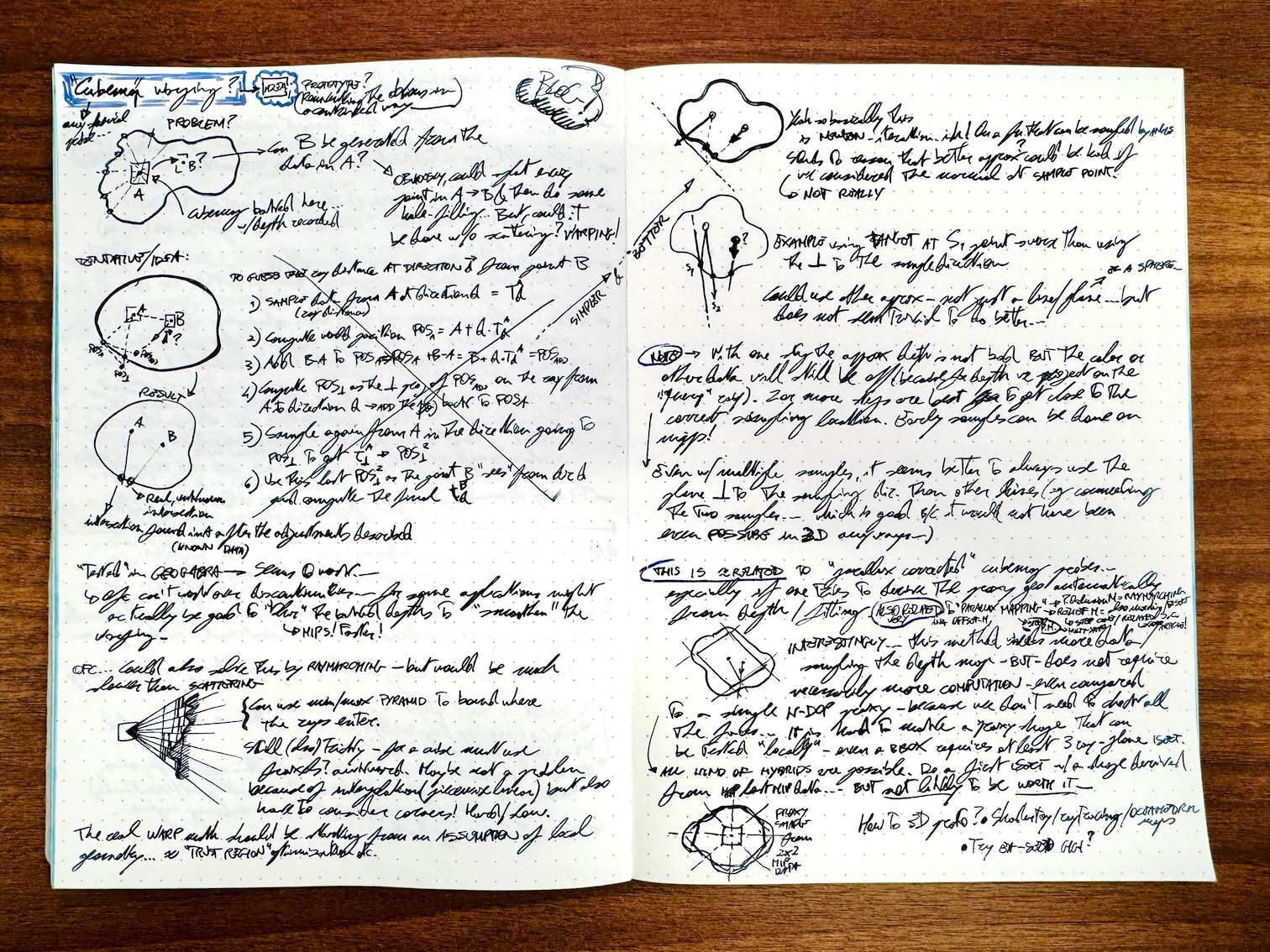
Doodling.
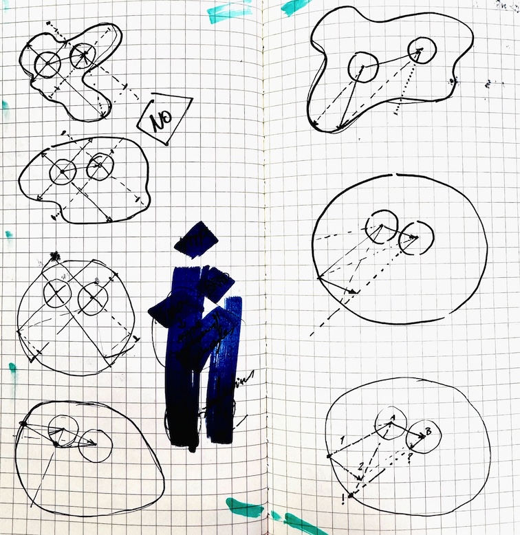 Some failed "attempts".
So, I've been working at this in my spare time, it's true... but most importantly, I've been working at it lazily. I started doodling around, trying to see if there was an obvious solution, and initially all my focus was on doing something based on the vector between the two probe locations.
In my mind I've always known that the right thing would have been to take a principled approach. Start with some assumption on the scene geometry, so that from any known point in the scene one could construct a representation for the nearby geometry. This would then be used to intersect that representation with the ray from the second probe location - the one we're interested in warping to.
But I resisted doing that, and instead tried random solutions, until I stumbled upon something that looked promising. A few more hand-drawn "test cases" later, I got something like this:
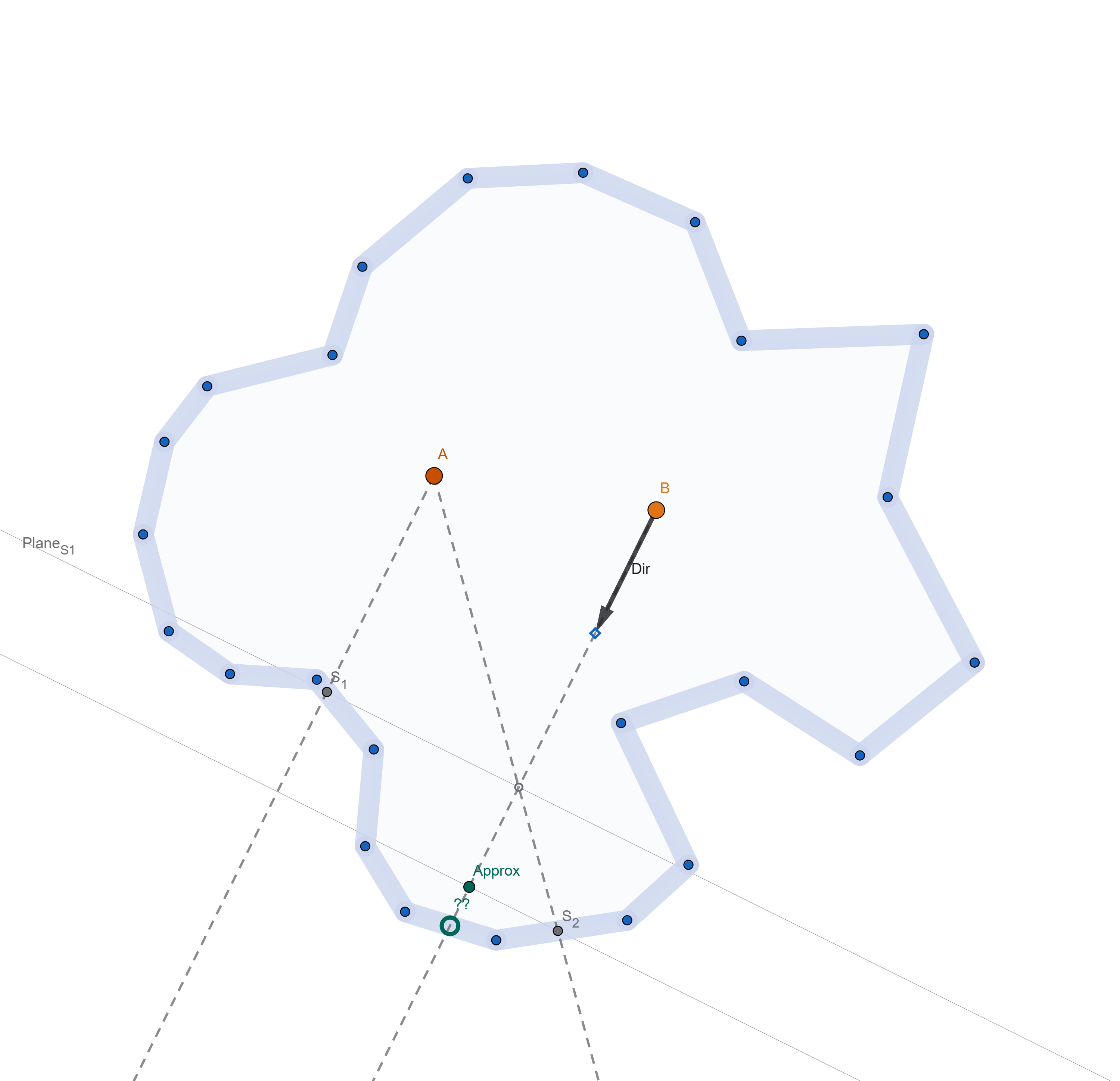 Solution, constructed in GeoGabra.
To know the ray intersection from B in the direction "Dir":
1) Sample the probe A in the direction Dir and construct the point S1.
2) Construct a plane perpendicular to the intersection direction, at S1.
3) Intersect a ray from B in the direction "Dir" with the plane - finding the point I
4) Sample A in the direction from A to I - to construct the point S2
5) Project S2 on the ray from B - and use that final point as the approximated intersection.
 Same algorithm again, testing a different direction.
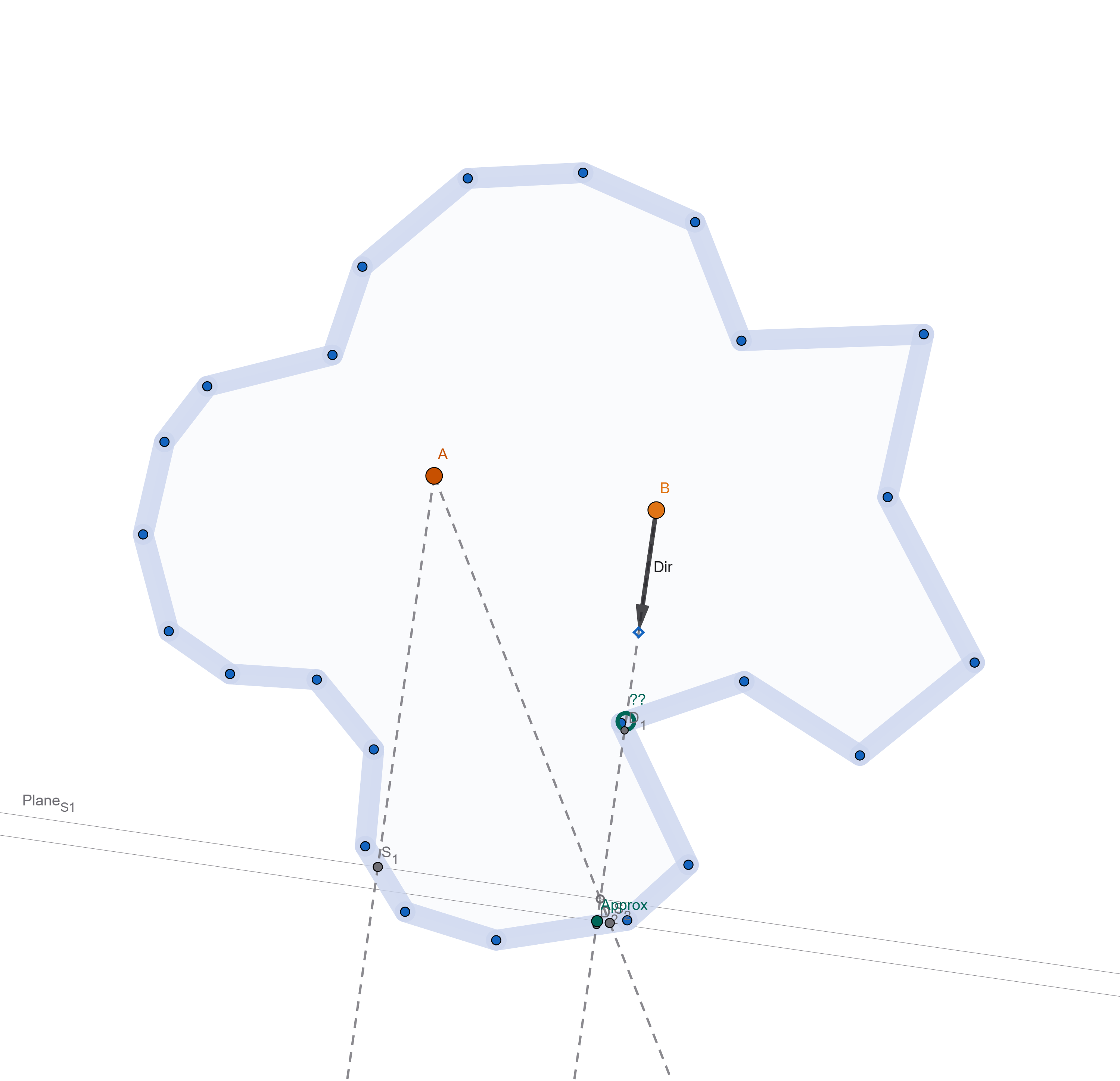 Obviously this fails with discontinuities. But such is life.
This seems to work suprisingly well, especially at approximating the depth of the intersection. If you look at the distance between the real point we would have intersected in the scene, and the one we fetch in the second probe query (4), it can still be quite off. But the "beauty" of this system is that you could repeat the steps one more time, to get an even closer approximation:
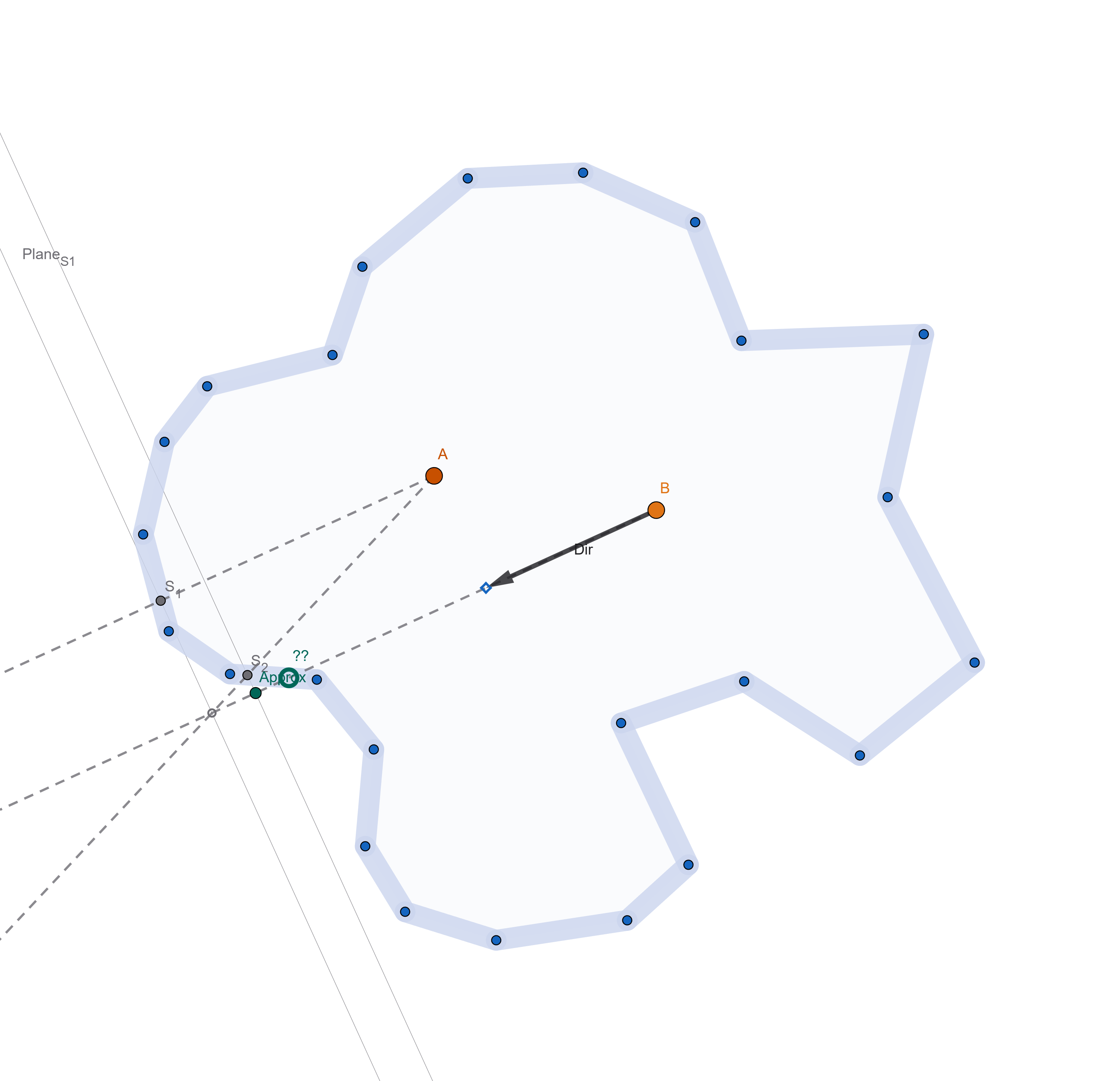
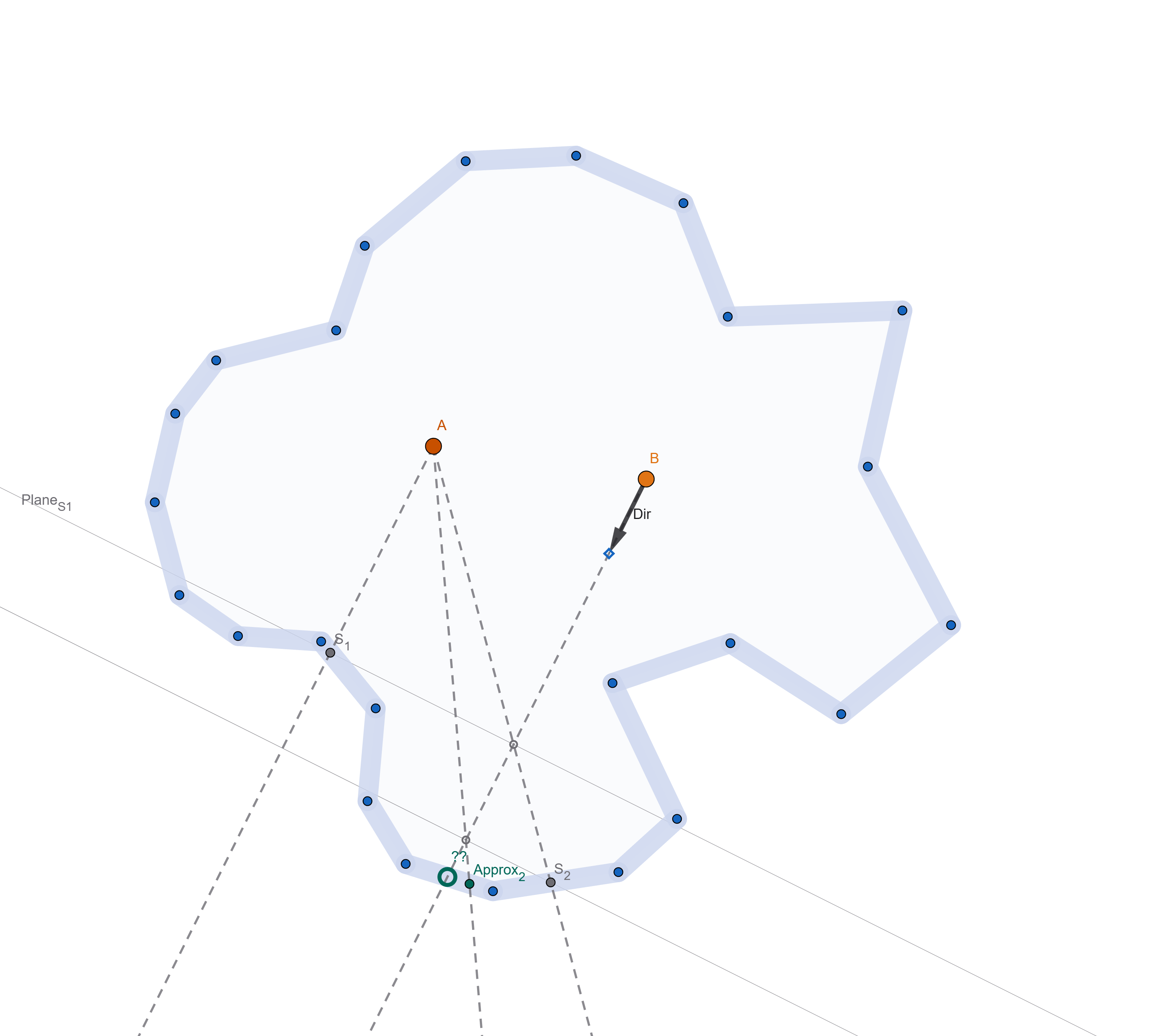 Taking an extra step/sample, we come much closer to the intersection point (S2 vs Approx2).
Smart? Well, we'll see about that.
First, if you cared to squint in the doodles I posted before, you'll notice I did not find this algorithm. Instead of constructing a plane perpendicular to the intersection (2), I was using a line from S1 in the direction of A-B. Which was not just dumb, but also more complex: lines and planes are the same in two dimensions but not in three...
I realized the error of my ways only when moving to GeoGabra as my first attempt of "testing" the idea.
Second, I started thinking that this was indeed a solution created from an assumption, namely, that the scene is mostly "flat", and it lies on some spherical surface we approximate with tangent planes... I even thought that this has some smell of numerical optimization, the "secant method", "trust regions" and so on...
But really...
Parallax mapping.
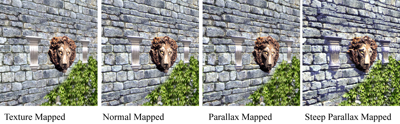
...this is a variant of parallax mapping. It's funny because I even just told the story of how I "reinvented" SSAO from relief mapping. And even back then it was the same, I knew there was lots of variants of relief/parallax, I knew you could march the a depthmap or use some math to roughly "warp" it... but I never bothered learning said math.
Only after blindly stumbling into something that seemed workable, I noticed the analogy, went back to finally learn the math... and yes, the algorithm above is basically parallax mapping - doing it multiple times is similar to "steep parallax mapping". Not exactly the same, but 99% similar. Oh well.
Sidenote: this whole parallax mapping business is truly confusing, with different people calling the same stuff in different ways. From what I could gather, the correct terms for the raymarching/binary search variants are "parallax occlusion mapping" or "relief mapping".
Vanilla "parallax mapping" should refer to warping with no marching, sometimes also called "offset mapping". Steep cone and relaxed steep cone mapping are optimizations that use distance information - similar to sphere tracing, but over heightfields.
Trying for real.
Alright, time to try in 3D. Again, I was resistant to this because I could not think of ways that would be quick and dirty... Here is the plan I mustered to do a prototype as simply as possible.
1) Use shadertoy :)
2) Rip a scene that looks complex enough and that can be raytraced (and of course I used something from IQ)
3) Bake a probe (in a shadertoy buffer) by raytracing, using octahedral mapping for simplicity. Shadertoy buffers are floating point, so storing the ray-intersectin parameter is easy.
4) Construct a second probe from the first, using the warping algorithm.
5) Profit? Display the warped probe in the scene on a sphere, maybe as a reflection map... If it works well enough, call it a day.
Not hard but still, some work to do. But thankfully... LLMs came to rescue! I just gave Gemini a path-tracing scene from IQ, asked to rip out the path tracing part, create a multi-pass shader that would bake the probe and use that data on a sphere to simulate reflections... And it worked!
 Various stages of... LLM grief.
In fact it worked so well that I started "pushing" the LLM with other, admittingly irrelevant requests. I had it add soft shadows to the sun, then convert from having a directional sun light to a point (sphere) light I could move around...
I had to give it some help with the octahedral mapping, but for the most part if was flawless. Which shouldn't be surprising, but let's be honest, it still is...
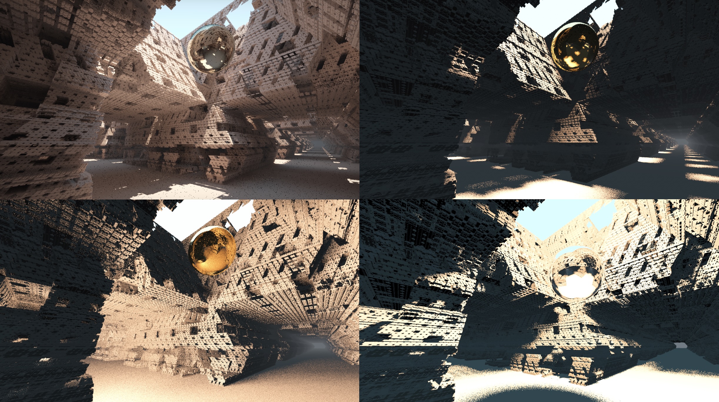
Anyhow, after Gemini created the test framework for me... I started coding for real. These are the final results:
(note that this scene is really a "torture test" as it is highly concave, with many discontinuities. I expect on more realistic scenarios this to work even better - likely one should always "pre-massage" the depth buffer to clamp and smoothen it appropriately)
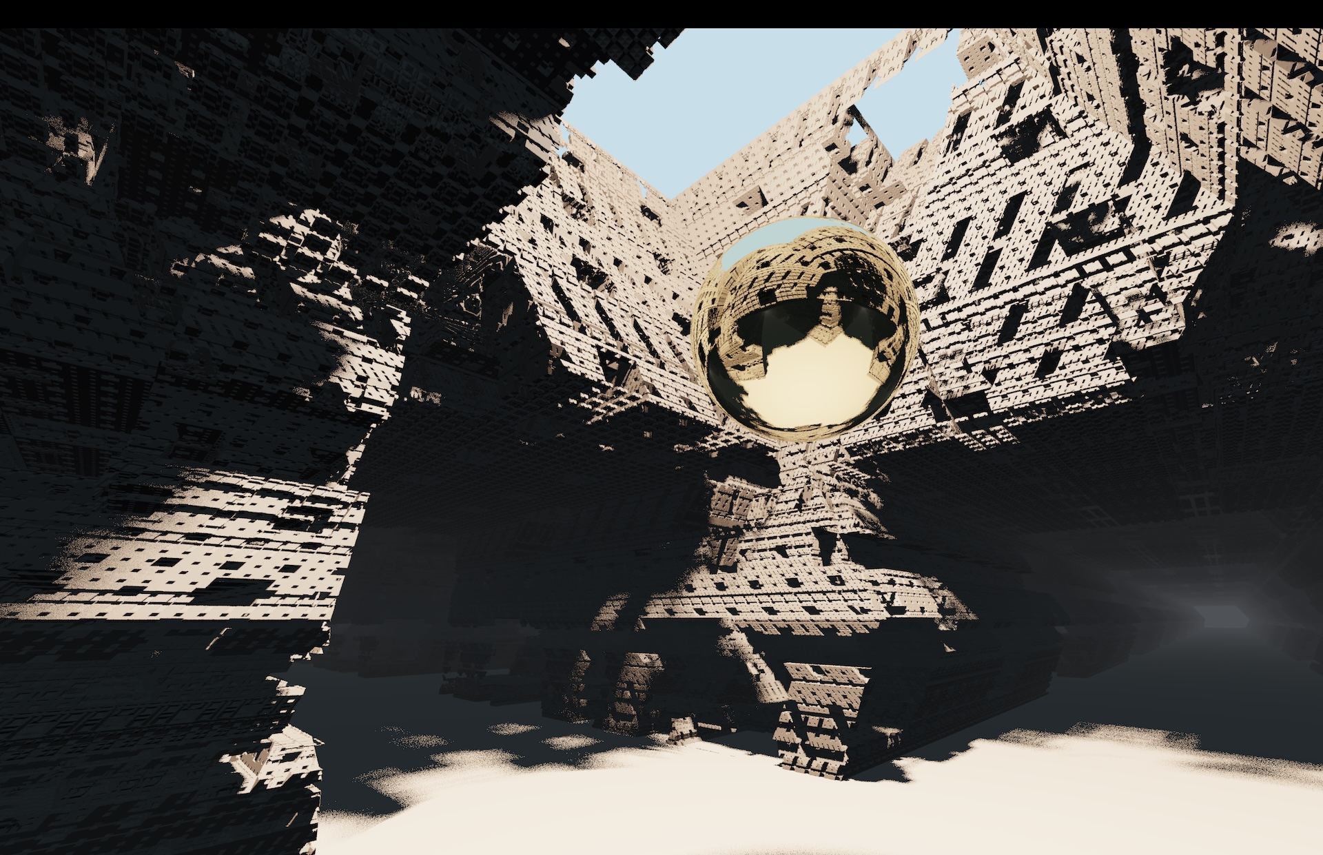 The baked probe at its original location.
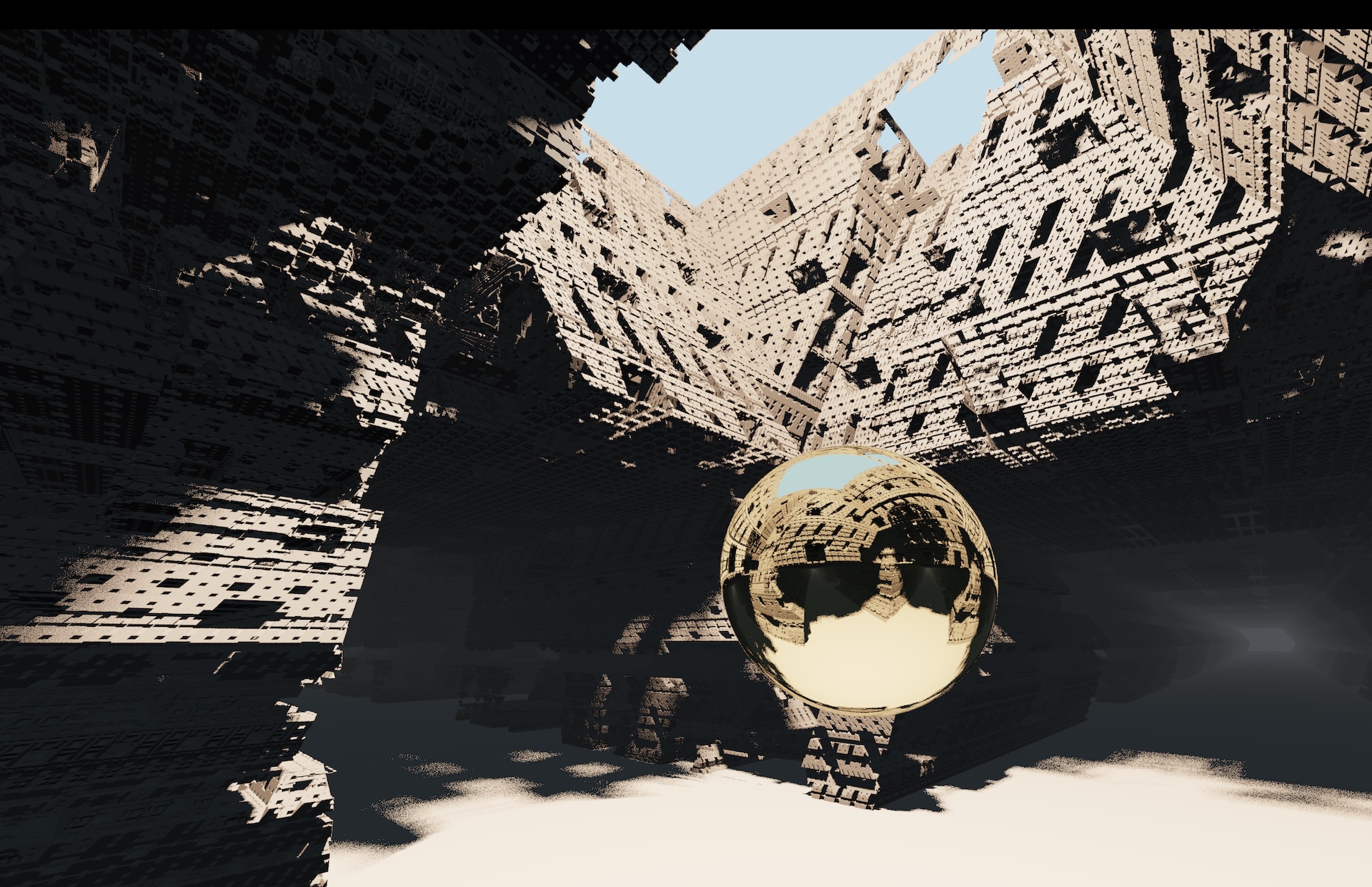 Directly using the data from the baked probe at a second location - no warping.
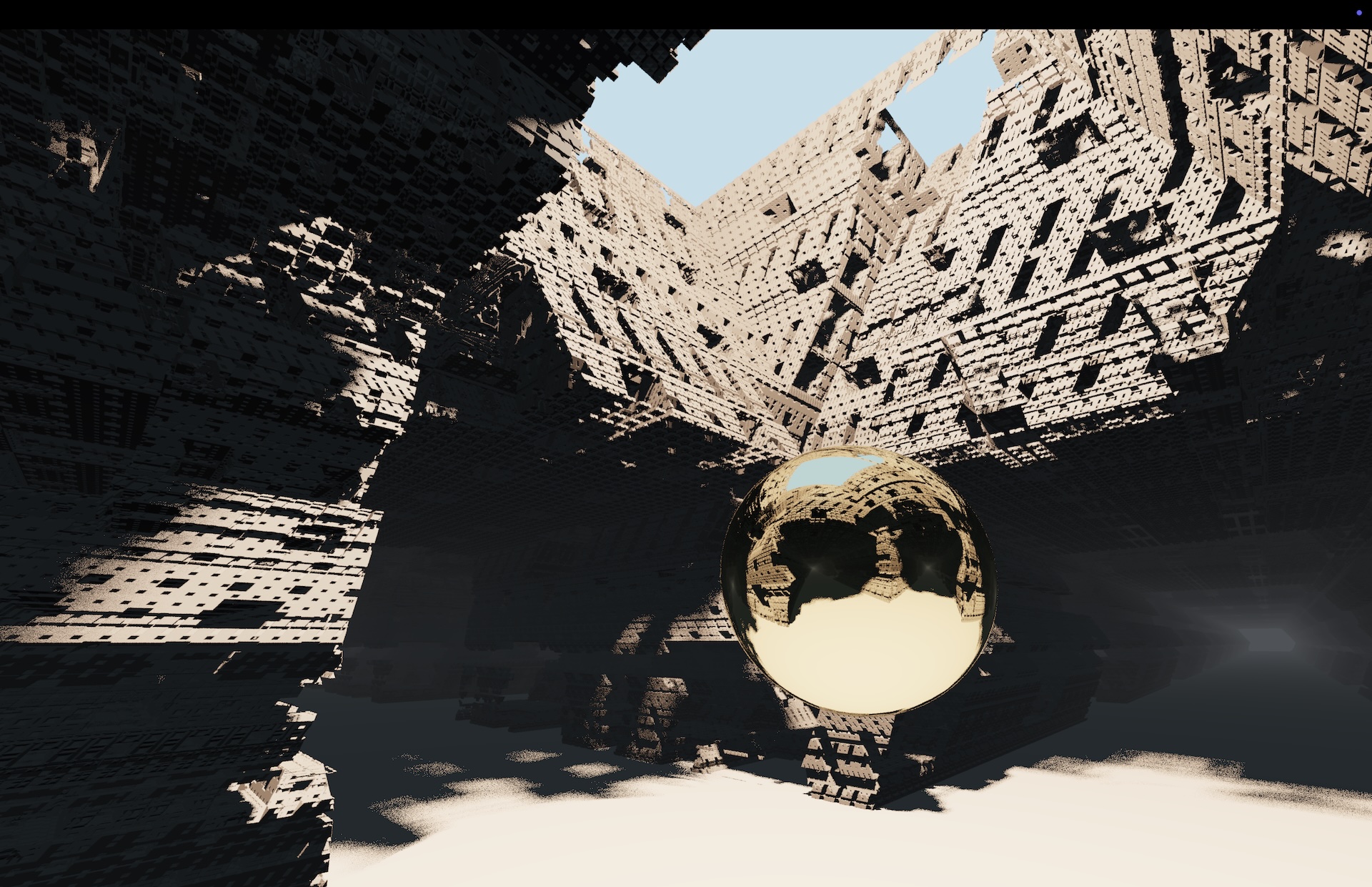 How it should really look like - reference solution obtained by baking at the second location.
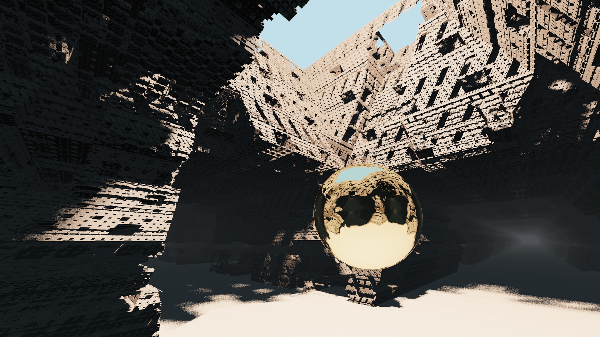 Results of the single-step warping.
Appendix.
I'm quite happy of how this turned out. Works surprisingly well especially for how fast it is. In fact - this is likely faster than the conventional way of "parallax corrected" cubemaps, that compute intersections with an analytic proxy shape. This is much less math! And even if you need to store and fetch depth, that information can be low-res, it's better if it is, remember - the algorithm does not love discontinuities...
In the screenshot above I'm using mipmaps (shadertoy automatically generates them for buffers if you set the sampler to mipmap) to use a "blurry" version of scene in the warping step - but just using mips with an octahedral map is far from correct.
Still, I wouldn't rush to use this for preconvolved specular probes, it likely needs to be improved to work there as specular probes are very sensitive to how you distort them, the change of speed of distortion (Jacobian) becomes clearly visible in the shaded results (that's why it's wise to either "fade out" the paralla correction at high roughnesses, or make the proxy shape "soft").
For some reasons, the two-steps correction looks worse than doing a single step - it distorts the image too much. Either I have to think of better approximations than projecting via planes, or for my use-case I could store the warped UVs first, then "relax" them (blur!) before using them to fetch data.
 This whole article, as notes in my notebook.
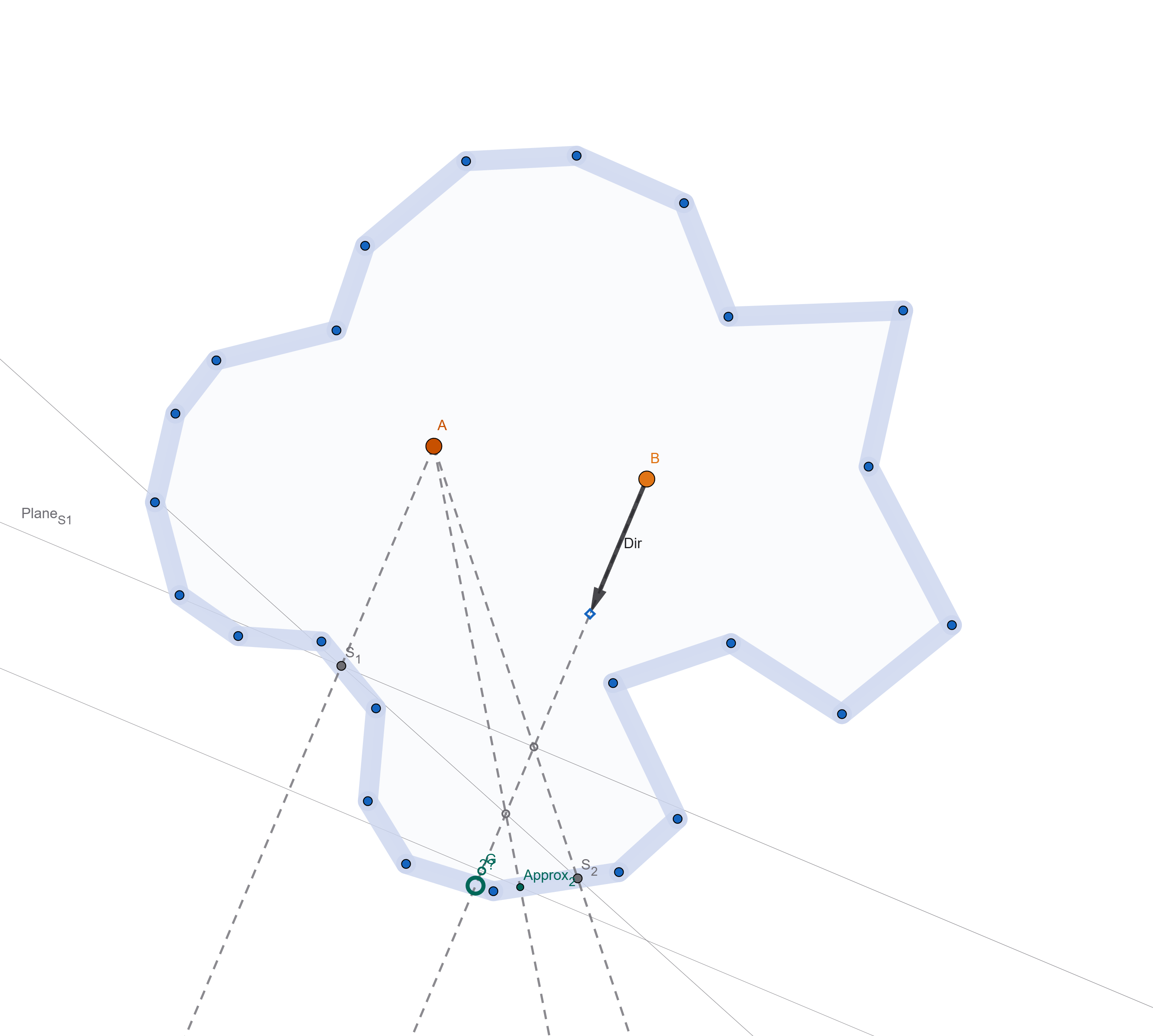 It seems worse to use, in the two-step process, a new plane perpedicular to the direction found in the first step, instead of always the same plane for both.
UPDATE: Simon Rodriguez over on Mastodon pointed me to "Approximate Ray-Tracing on the GPU with Distance Impostors", which is pretty much the same! Yet another case of a technique I knew about, but did not look in detail enough back then to be able to recall it 20 years later, and avoid re-discovering stuff :)
In the paper, they keep constructing planes from the previous two approximated intersections, which I found not to be worth doing in my case. I suspect the difference is that if you're trying to converge the method to the true intersection, then that works best (and you could even think of higher order interpolating surfaces), but in my case I am more interested in keeping the warping "stable" than accurate.